Table of Contents
Introduction
Grease traps, also known as separation tanks, are essential wastewater pretreatment structures designed to remove floatable oil substances from oily wastewater. They operate on the fundamental principle of density difference, allowing oil droplets to separate and float to the surface while heavier solids settle. Proper grease trap installation is not merely a regulatory requirement in many regions, particularly for establishments like restaurants and food processing facilities that generate significant amounts of oily wastewater. It is a critical investment that safeguards plumbing systems from clogs, prevents environmental contamination, and ensures compliance with discharge standards.
Shandong Lushun Environmental Technology Co., Ltd., for instance, specializes in high-tech environmental protection products, including food wastewater treatment systems that efficiently remove organic matter, grease, and suspended solids, highlighting the broader importance of effective grease management. This blog post will guide you through seven crucial steps to ensure the best grease trap installation practices, drawing on industry standards and practical advice to help you achieve efficient and compliant wastewater management.
Understanding Grease Trap Installation: Types and Planning
Before diving into the installation process, it is crucial to understand the different types of grease trap installation and the initial planning required. The primary goal of any grease trap installation is to efficiently remove oil and grease, which often exist in wastewater in suspended, emulsified, or dissolved states, with suspended oil being the easiest to separate.
Types of Grease Trap Installation
The installation of grease traps primarily falls into three categories, each suited to different operational needs and spatial constraints:
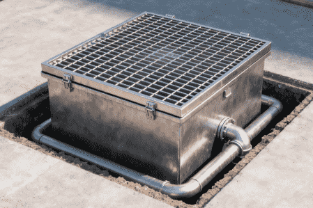
• Above-Ground Grease Trap Installation: This type of grease trap installation typically involves placing the unit in a dedicated equipment room. Such an arrangement allows for easier access for maintenance, cleaning, and inspections. It is crucial to include provisions for emergency drainage during above-ground grease trap installation to facilitate cleaning or repair activities.
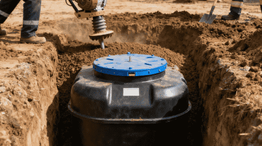
• Underground Grease Trap Installation (Buried Grease Trap): Often chosen for outdoor environments or when space is limited indoors, underground grease trap installation requires excavating a pit according to the equipment’s dimensions. The pit walls are commonly constructed from brickwork or concrete for protection and structural integrity. Sufficient space must be reserved around the grease trap for pipeline connections at both ends.
• Under-Sink Grease Trap Installation: This is a common choice for smaller catering operations where the grease trap dimensions are compact. Under-sink grease trap installation involves placing the unit directly beneath the kitchen sink or within the kitchen area itself, offering a direct and immediate point of separation for grease.
Effective grease trap installation begins with careful planning, considering the volume of wastewater, the concentration of oil and grease, and local regulations. The choice of grease trap type—be it flat-flow, parallel plate, or inclined plate—also influences the installation requirements and overall efficiency. Flat-flow grease traps, for example, are designed for slow horizontal flow, allowing oil to separate and float to the surface.
How to Install a Grease Trap: General Guidelines
Regardless of the specific type, certain general principles apply to every grease trap installation to ensure optimal performance and longevity. The installation process is not just about placing the unit but integrating it seamlessly into the existing plumbing and wastewater treatment system. Shandong Lushun Environmental Technology Co., Ltd. emphasizes integrated solutions for wastewater treatment, where each component, including the grease trap, plays a vital role in the overall system’s efficiency.
Key Aspects of Grease Trap Installation:
1. Site Selection and Preparation: For underground grease trap installation, this involves civil engineering work to excavate the equipment pit. The pit bottom must be hardened and capable of bearing weight, with surrounding walls (preferably brick or concrete) for protection. Adequate space around the grease trap is necessary for pipe connections.
2. Equipment Placement and Leveling: Once the site is prepared, the grease trap equipment is carefully lowered into the pit (for underground) or positioned in its designated spot (for above-ground or under-sink). It is critical to adjust the grease trap to a perfectly horizontal position to ensure proper flow and separation.
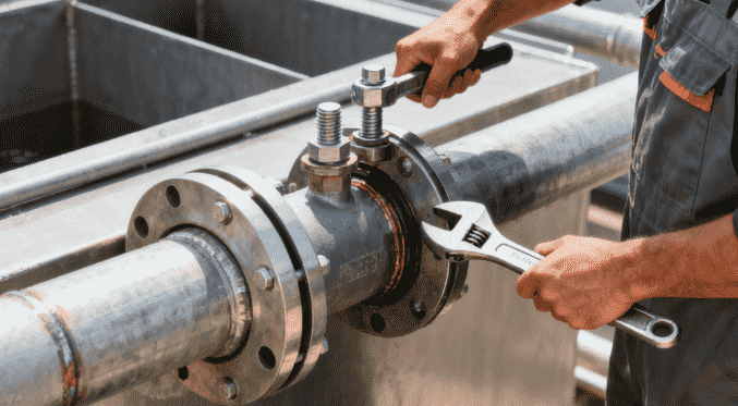
3. Piping Connections: The inlet and outlet pipes are connected to the grease trap, often using clamps. During grease trap installation, meticulous attention must be paid to the flow direction; the inlet and outlet should never be reversed.
4. Initial Setup and Water Filling: Before the first use, the grease trap should be filled with tap water. The water level regulating pipe then needs to be adjusted so its top aligns with the upper edge of the oil overflow trough. The inlet pipe should also be positioned at a suitable distance from the debris separation box to allow for easy removal.
5. Backfilling (for Underground Installation): After the grease trap is filled with water, the space between the grease trap and the pit walls is backfilled with a dry mixture (e.g., yellow sand and cement in a 4:1 ratio). A small amount of water can be added during mixing to prevent dust, but it should not be wet enough to become a flowing slurry, which could deform the equipment. The backfilling should reach the height of the bottom of the inlet and outlet pipes and then be lightly compacted.
6. Protective Cover Installation: Depending on the location of the equipment pit and the expected traffic (pedestrian, light vehicle, or heavy vehicle), an appropriately load-bearing, segmented, and openable protective cover should be installed. This cover facilitates daily oil and sludge removal by maintenance personnel.
7. System Testing and Adjustment: After the grease trap installation is complete, introduce oily wastewater into the system. The water level regulating pipe should be adjusted again until the oil drain pipe only discharges oil and no water. If the oil drain pipe is too low, the cover can be opened, and oil removed manually.
Design and Regulatory Compliance for Grease Trap Installation

Adhering to design standards and fire safety regulations is paramount for any grease trap installation, ensuring both operational efficiency and safety. These regulations cover various aspects from sizing to material specifications, aiming to prevent hazards and maintain environmental integrity. Shandong Lushun Environmental Technology Co., Ltd. prides itself on developing and launching competitive environmental protection products, underscoring the importance of innovative solutions that meet stringent design and safety requirements.
Key Design Parameters for Grease Trap Installation:
Several national standards, such as GB50015-2019 “Standard for Design of Building Water Supply and Drainage,” GB50684-2011 “Design Code for Chemical Industry Wastewater Treatment and Reuse,” and GB50160-2008 “Code for Design of Fire Protection for Petrochemical Enterprises,” provide detailed guidelines for grease trap installation and operation.
| Parameter | Standard / Recommendation | Applicable Grease Trap Type |
| Drainage Flow Calculation | Should be calculated based on the design second flow rate. | All grease trap installations. |
| Wastewater Flow Velocity (edible oil) | In the tank, flow velocity should not exceed 0.005m/s. | All grease trap installations for edible oil. |
| Wastewater Retention Time (edible oil) | In the tank, retention time should not be less than 10 minutes (for GB50015-2019). For flat-flow grease traps in chemical industries, it is recommended to be 1.5h2h. For general edible oil wastewater, it is 210min. | All grease trap installations, with specific recommendations for different types/industries. |
| Oil Storage Volume (manual removal) | The volume of the oil storage part should not be less than 25% of the effective volume of the tank. | Manual oil removal grease trap installations. |
| Cover Material | Should be made of non-combustible or hard-to-burn materials. | All grease trap installations. |
| Water Seal Height | Inlet/outlet pipes should have water seals. Water seal height should not be less than 250mm (GB51283-2020, GB/T51248-2017), or 400mm (GB50160-2008, GB51261-2019). | All grease trap installations with water seals at inlet/outlet. |
| Outlet Pipe Depth | The bottom of the outlet pipe to the bottom of the tank should not be less than 0.6m. | All grease trap installations. |
| Protection Height | The protection height (above liquid surface) should not be less than 400mm. | All grease trap installations. |
| Number of Compartments | Should not be less than 2 compartments, and each compartment can operate independently. | All grease trap installations. |
Fire Safety and Material Specifications for Grease Trap Installation:
• Cover Specifications: Grease trap covers must be made of difficult-to-burn or non-combustible materials. For enclosed tanks, the space above the liquid surface is classified as Zone 0 for explosion hazard. Covers and their seats for inspection wells within 5m of the grease trap must be sealed, and covers should not have holes.
• Water Seals: All inlet and outlet pipes of grease traps must be equipped with water seals to prevent the backflow of gases. The height of these water seals is specified to be not less than 250mm or 400mm, depending on the specific standard and application.
• Hazardous Area Classification: For flammable liquids, specific explosion hazardous areas are defined around grease traps. For uncovered traps, the space above the liquid and within 1.5m horizontally and 1.5m vertically above the tank top is classified as Zone 1, extending further to Zone 2.
• Heating Facilities: In cold regions, or when the solidification point of the separated oil is higher than the ambient temperature, heating facilities should be provided at the oil collection pipe to prevent oil solidification.
• Firefighting and Safety Measures: Grease traps should be equipped with firefighting facilities. Furthermore, electromechanical equipment associated with grease traps (or tanks) must implement explosion-proof measures and be fitted with anti-static grounding facilities.
• Location: Grease traps should ideally be located outside the kitchen discharge pipe. For specific industrial settings like petroleum storage, dedicated grease traps for a tank group may be located within its fire dike, with capacity limits. However, for urban rail transit, setting septic tanks and grease traps on elevated platforms is not recommended.
By strictly adhering to these design and safety regulations, businesses can ensure their grease trap installation is not only efficient in wastewater treatment but also safe and compliant, contributing to sustainable and eco-friendly operations.
How Do You Install a Grease Trap: Practical Steps
Implementing a grease trap installation correctly involves a series of practical steps, ensuring that the system functions as intended and meets all regulatory requirements. These steps build upon the general guidelines and design principles discussed earlier, focusing on precise execution.
Step 1: Conduct Thorough Site Assessment and Preparation
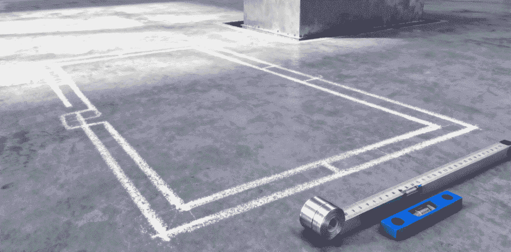
Before commencing any grease trap installation, a comprehensive site assessment is crucial. This involves evaluating the location for the chosen grease trap type (above-ground, underground, or under-sink). For underground grease trap installation, this means accurately determining the excavation site. The pit should be dug to the precise dimensions of the equipment, allowing additional space for pipe connections and maintenance access. For all types, ensure the site can support the weight of the filled grease trap. For underground installations, the pit bottom should be hardened and capable of bearing the load, with surrounding walls (e.g., brick or concrete) for protection.
Step 2: Ensure Adequate Foundation and Support
Once the site is prepared, focus on the foundation. For above-ground grease trap installation, a level, sturdy base is required. For underground grease trap installation, the hardened pit bottom provides the foundation. It is vital that the base is perfectly level to facilitate efficient oil separation within the trap, as an uneven installation can hinder the natural gravitational separation process. Surrounding walls, if used, should be structurally sound to protect the equipment and prevent collapse.
Step 3: Carefully Place and Level the Grease Trap Unit
With the foundation ready, the grease trap unit can be positioned. For underground units, carefully lower the equipment into the pit. Regardless of the installation type, the grease trap must be meticulously leveled. Use a spirit level to ensure that the unit is perfectly horizontal. This horizontal alignment is paramount for the efficient flow of wastewater and the effective separation of oil and grease. Incorrect leveling can lead to short-circuiting of flow, reducing treatment efficiency.
Step 4: Connect Inlet and Outlet Piping Correctly
This is a critical stage in the grease trap installation process. Connect the wastewater inlet pipe to the grease trap’s inflow port and the treated water outlet pipe to its outflow port. Connections are often secured with clamps or other appropriate fittings. Crucially, pay extremely close attention to the flow direction. The inlet and outlet must not be reversed. The inlet pipe should be positioned to allow easy removal of the debris separation box, which typically sits at the entrance of the grease trap. Water seals are also essential at the inlet and outlet pipes to prevent gas backflow, with specified heights not less than 250mm to 400mm depending on the standard.
Step 5: Perform Initial Water Fill and Adjust Water Level
Before introducing any oily wastewater, fill the newly installed grease trap with clean tap water. This initial fill helps in setting up the system correctly. Next, adjust the water level regulating pipe. The top of this pipe should be level with the upper edge of the oil overflow trough. This adjustment ensures that once oily wastewater is introduced, oil will effectively accumulate and overflow into the collection system, while water remains within the trap for further separation.
Step 6: Backfill and Compact (for Underground Grease Trap Installation)
For underground grease trap installation, after the unit is filled with water and pipes are connected, the surrounding pit needs to be backfilled. Use a dry mixture, such as a 4:1 ratio of yellow sand to cement. A minimal amount of water can be added to the mixture to prevent dust, but it must not be wet enough to become a flowing, squeezable state. This is vital to prevent the mixture from exerting excessive pressure on the grease trap, which could lead to deformation. Lightly compact the backfill until it reaches the level of the bottom of the inlet and outlet pipes.
Step 7: Install Protective Cover and Implement Safety Features
The final step in the grease trap installation is to install the protective cover. For underground units, this involves a load-bearing, segmented, and openable cover, designed to accommodate the expected traffic at the location (pedestrian, light, or heavy vehicle). This cover allows for convenient access for daily maintenance, such as oil and sludge removal.
For all grease trap installations, ensure that the cover material is non-combustible or hard-to-burn and that it forms a tight seal to prevent accidental fires, oil volatilization, and the ingress of dirt. If located in a cold region, consider installing heating facilities at the oil collection pipe to prevent oil solidification. Furthermore, any associated electromechanical equipment must have explosion-proof and anti-static grounding measures, and appropriate firefighting facilities should be in place.
Conclusion
Proper grease trap installation is an intricate process that demands meticulous planning, adherence to design specifications, and strict compliance with safety regulations. From selecting the right type—be it above-ground, underground, or under-sink—to executing the seven crucial steps of site preparation, accurate placement, precise piping, and final safety measures, every detail contributes to the system’s efficiency and longevity. The goal is not just to install a piece of equipment but to integrate a solution that effectively prevents pipe blockages, mitigates environmental pollution, and ensures businesses meet their discharge standards.
The detailed guidelines provided by various national standards emphasize the importance of features like proper flow velocity, adequate retention time, robust cover materials, and essential safety provisions like water seals and fire protection. By prioritizing professional installation and diligent maintenance, businesses can maximize the benefits of their grease trap system, achieving both environmental stewardship and operational cost savings. A well-executed grease trap installation is a testament to a commitment to sustainable practices and responsible waste management.
FAQ
Q1: What are the main types of grease trap installation?
A1: The main types of grease trap installation are above-ground, underground (also known as buried), and under-sink. Each type is chosen based on the available space, the volume of wastewater, and specific operational requirements.
Q2: What is the primary purpose of a grease trap?
A2: The primary purpose of a grease trap is to separate and remove floatable oil and grease from wastewater before it enters the main sewage system. It utilizes the density difference between oil and water, allowing oil to float to the surface for collection. This prevents pipe blockages and reduces environmental pollution.
Q3: Why is a water seal important in grease trap installation?
A3: Water seals are crucial at the inlet and outlet pipes of a grease trap to prevent the backflow of odorous gases or hazardous fumes from the sewage system into the building or environment. Various standards specify a minimum water seal height, typically ranging from 250mm to 400mm.
Q4: How often should a grease trap be maintained after installation?
A4: While the sources do not specify a frequency, they mention that grease traps should have movable covers to allow for daily oil and sludge removal. Regular maintenance, including cleaning and inspection, is essential to ensure the continued efficiency and proper functioning of the grease trap.
Q5: What are the key design parameters to consider for efficient grease trap installation?
A5: Key design parameters include calculating drainage flow, ensuring the wastewater flow velocity in the tank does not exceed 0.005m/s, maintaining a wastewater retention time of at least 10 minutes (or 1.5-2 hours for certain types), and ensuring the oil storage volume is at least 25% of the effective volume for manual removal types.